Control Valve (CV)
How does a control valve work?
A control valve, or regulation valve, serves as an actuator in a control loop. As a throttle device, it enables the desired volume of flow to be set in a pipeline. Control valves from STÖHR ARMATUREN control the flow in a process plant. For this purpose, the valve stem (spindle) is connected to the valve cone. This closes the valve seat ring by resting against the media pressure. When the spindle moves up, the flow opens and increases the flow rate depending on the profile of the control cone.
What are the physics during the control process?
Closing the flow narrows the cross-section of the flow. The pressure of the medium decreases, and its flow rate increases. After the cross-sectional constriction, the velocity of the medium returns to around its former value, assuming the pipe diameter before and after the throat is the same, though it is common for a pressure drop ("ΔP") to remain. This can be indicated as a characteristic value. The geometric shape of the cone determines the flow characteristic. This can be carried out in a linear or equal percentage manner, or according to customer-specific requirements.
How is precise regulation achieved?
Control valves are typically controlled by an automated actuator. Manual control valves may be used, but these are less accurate. Most actuators are pneumatic, but electrical and solenoid actuators are also available. In addition to the pneumatic actuator, a control valve is usually equipped with a position controller (IP controller), and a limit switch may be used as backup.
Check Valve (CHK)
How does a check valve work?
A check valve is a valve that opens the flow of the medium in only one direction – the flow direction – and closes against the recirculating flow of media. The medium can be both in gaseous or liquid state.
How does the closing process work on the check valve?
In spring-loaded check valves, the shut-off element takes the form of a plate, ball or cone which opens the valve when the media begins to flow in the intended direction, creating a pressure that’s greater than the closing force of the spring. This spring closes the shut-off element when the media pressure falls below the closing pressure of the spring force, or when the medium flows in the opposite direction.
A spring-less check valve – such as the STÖHR Magros Series 1500 – opens its valve plug when the pressure of the media flow is greater than the forces of attraction of the magnet located in the valve housing. As the opening increases, the force needed to open the cone further reduces. Thus, the energy loss at fully open poppet is comparatively lower than that of a spring-loaded check valve. Unlike the spring, the magnet is not subject to material fatigue or wear, and hence magnetically loaded check valves can be described as being maintenance-free.
How does an axial overflow check valve work?
An overflow valve is an axially aligned valve in which the medium flows along the direction of construction. The media pressure prevents the closing of the valve by pressing a ball against a spring. As soon as the media pressure falls below the spring force, the valve closes. In the open state – in which the spring tension is less than the media pressure – the medium flows past the ball on the valve seat (overflow).
Globe Valve (GV)
How does a globe valve work?
A globe valve – often referred to as an open/close valve or shut-off valve – controls the opening and closing of flow openings or medium pipes, and is used to regulate the flow in fluid and gas installations. Globe valves are operated manually using a hand wheel, by a motor, or by an external drive, which can be pneumatic, electric or magnetic. While ball valves are shut off with a hand movement, the flow is continuously throttled by axial rotation of the spindle in stroke valves, while the cross-sectional area of the valve opening is gradually reduced until the shut-off cone rests flat on the valve seat and interrupts the media flow.
Can a globe valve also be used for flow regulation?
The globe or shut-off valve is intended to achieve both full flow and full shut-off of flow. To achieve shut-off, a shut-off cone rests flat on the valve seat and is pressed against the medium flow. A controlled medium flow is not possible with a shut-off valve.
Filter (STR)
How does a gas filter work?
In fluid technology, a filter or strainer retains solids from a gas or liquid flow – much like a sieve. The solid-free phase is usually referred to as filtrate in the filtration of liquids, and in gas filtration as pure gas. Filtration is especially important in the gas phase, where gas flows through the valve seat into a filter cartridge and is pushed through the filter meshes.
What happens during the filtration process?
The driving force of filtration is the pressure difference that occurs in the transport medium before and after the filter. The medium is pressed through the filter with excess pressure. Once the medium has passed through the filter, a pressure drop ("ΔP") occurs. The smaller the filter mesh, the higher the resulting pressure loss. It may be possible to minimise this loss of pressure by enlarging both the filter housing and the filter insert (also known as the filter cartridge).
What filter mesh sizes does STÖHR ARMATUREN offer?
Gas filters consist of a permeable filter mesh made of stainless steel wire of different qualities welded to a steel ring at the top and bottom. The fabric may have different-sized passages, the spacing of which is typically between a minimum of 3μ and a maximum of 100μ – often referred to as mesh size. The standard mesh size for filters from STÖHR ARMATUREN is 40μ. Other mesh sizes are available on request.
Can a polluted filter be cleaned?
If a filter insert becomes polluted, it can easily be removed from its housing, cleaned with distilled water or nitrogen, and reinstalled. Start by depressurising the pipe, then loosen the screws in the housing on top of the filter and remove the filter cartridge. After cleaning, the filter cartridge can simply be screwed into a thread at the seat, or inserted without threading. See the operating and maintenance manual for full details.
Purge Valve
Why are purge valves installed in a pipeline?
Purge valves are used to clean fittings and pipes by flushing them with gas (mostly nitrogen). For this purpose, the gas enters the pipe through a purge valve, and exits downstream.
The rinsing process may be required for different reasons:
- After system set-up, to remove welding residues
- To remove humidity from the pipe
- Before changing the medium within the pipe
Where are flush valves installed?
The positioning of purge valves within the plant is determined by the design engineer. When mounted onto the main valve, they can be positioned in flow direction upstream on the right or left of the inlet, and correspondingly downstream on the right or left of the outlet. Purge connections can be welded to the main valve ready for purge valves to be added at a later stage. Note that the installation of purge valves or purge connections may change the overall length of the main valve.
Which purge valves are used by STÖHR ARMATUREN?
We source high-quality purge valves from well-known manufacturers. The brands and products we use are listed in our product catalogue or contained in your offer.
If you prefer manufacturers or types other than those we offer as standard, please let us know and we will check for alternatives.
End connections
Which end connections are STÖHR valves equipped with as standard?
The standard form of the end connections are welding ends in accordance with DIN, EN, ISO, ASME or other standards. The dimensioning of the connections provided is specific to each nominal diameter, as shown in the technical data tables on the catalogue pages of the valve.
What non-standard end connections are available?
Welding ends can also be supplied to your needs, according to standards other than DIN. Enter the precise connection dimension you require in your request for quotation (RfQ). Other forms of connection – such as flanged, screwed or compression fittings – can be supplied to your specifications if they are available on the market. Alternatively, you are welcome to supply your own connections, and we will charge you for welding these to your valves.
Welding flange
What welding flange diameters are STÖHR ARMATUREN valves equipped with as standard?
Welding flanges are only available for cryogenic valves. Diameters vary according to the valve series.
Standard diameters can be found in the table below.
Bespoke diameters can be manufactured and supplied to suit your specifications.
Please provide precise dimensions in your request for quotation to STÖHR.
Bellow
What are the features of the bellows actuator?
STÖHR ARMATUREN has designed a bellows-driven pneumatic actuator especially for applications with radiation.
This development avoids damage to plastic parts and ensures maintenance-free operation without gas emissions to the environment.Special feature:
- radiation proof
- maintenance-free
- free of gas emission
What is a bellow?
A bellow is an elastic, accordion-like folded metal tube made from one or more nested very thin tube(s) by controlled upsetting, giving it an outer shape of rounded waves. Metallic bellows are used as a thermal or structural compensating element in pressure vessels and pipes. The metallic ends can be welded, enabling a high-quality sealing of the valve spindle to the outside. The resulting leakage for STÖHR valves is 1x10E-8.
How is a valve sealed to the environment?
There are several ways to seal the movable spindle to outside. For most of our valve series, we use a metallic bellow as the first stem seal, and metal rings or O-rings as the second spindle sealing – providing a further seal to the outside should the bellow fracture.
Valve stem extension
Why do cryogenic valves have an extension of the valve stem?
The extension of the valve stem is required to protect the actuator against the freezing and external icing that occurs due to the cold of the liquid gas.
When starting a cryogenic media flow, the heat input of the still uncooled pipe or fitting briefly creates a gas cloud from the liquid media stream by heat input, and the gas cloud rises up the valve stem. Once the liquid gas follows, the gas cushion is usually maintained. This prevents the liquid gas from rising to the top of the valve stem and hindering the mobility of the actuator by freezing – at which point it would become impossible to close the valve. Cryogenic valves must be installed in an upright position, with the actuator facing upwards, and a maximum of 30° lateral inclination. If the slope is greater than 30° a longer stem extension is required to prevent freezing.Are the specifications for the mounting position of a valve compulsory?
Cryogenic valves must be installed in an upright position, with the actuator pointing upwards and a maximum of 30° lateral inclination. At a greater incline, with a horizontal installation position (an incline of around 90° to the vertical axis) or an overhead installation (an incline of around 180° to the vertical axis), the gas cushion would escape via the media pipe. If this installation position is necessary from a system design perspective, (where space is tight or improved access for operation is needed) our TD valve variant must be selected for series 900 or 1200 (FREES) to permit this.
What is the stem extension of a valve?
The stem extension measures the length of the extension of a cryogenic valve stem from the centre of the pipe to the bottom of the welding flange. Typical stem extension dimensions must not be significantly undercut, to prevent the actuator from freezing. If a longer extension is required for plant design or space reasons, get in touch. We may be able to create a bespoke extension, subject to manufacturing limitations.
Why does the stem extension of different cryogenic valves differ in length?
The length of the valve stem is selected to avoid freezing of the actuator at a professional installation position. The extension is calculated on the basis of the expected heat input. Different nominal widths and housing shapes result in different extensions of the valve stem.
What should be considered when specifying a control cone?
The geometric shape of the control cone determines the flow characteristic of this valve. Our control valves are equal percentage as standard but can also be designed as linear or customer-specific flow characteristic, and can be adapted by mounting a valve plug with a suitable profile.
As well as the flow characteristic, the flow ratio determines the control characteristic of the valve. The control ratio describes the ratio between minimum and maximum achievable flow, with a ratio of 1:30 for a simple control and 1:50 for a more precise control – reaching up to 1:100, where 100 steps are available between the closed state and full opening of the valve cone for adjustment. The larger the stroke of the valve – in other words, the distance between the valve seat and full opening, measured in millimeters – the more accurately the media flow can be regulated.
Vacuum insulation
Are STÖHR valves suitable for installation in vacuum-insulated pipes?
The installation of a cryogenic valve into a vacuum-insulated line allows a massive reduction of the heat input from the immediate environment into the valve. Vacuum insulation is usually combined with an insulation by wrapping a multilayer insulation folio (MLI) against thermal radiation around. The vacuum housing is connected to the valve at the welding flange. Most STÖHR cryogenic valve series are suitable for installation in vacuum-insulated lines. In addition to the welding flange, they are designed to prevent the valve leaking to the outside, and thereby breaking the vacuum. Use our product configurator to check the individual suitability of the selected valve series.
Does STÖHR ARMATUREN supply valves with vacuum-insulated housing?
Our cryogenic valves for installation in vacuum-insulated piping systems can be delivered with housing ex-works as an option. The valve body is wrapped in a multilayer folio for superinsulation for high thermal quality. The housing is made of stainless-steel tubes that are welded to the welding flange. The jacketed valve can be installed in rigid or flexible transfer lines without further preparation. For this purpose, the valve is either configured with an end connection for welding or with a coupling. Please specify the precise dimensions you require on your request for quotation.
Mounting parts
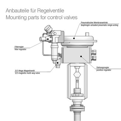
Which mounting parts are attached to a pneumatic valve?
What function does a pilot valve have?
A pilot valve is an electromagnetic shut-off valve that controls the air flow in and out of the pneumatic actuator (piston or diaphragm type). As a result, the volume of air in the chamber of the pneumatic actuator increases or decreases, indirectly triggering a vertical movement of the valve stem against a spring resistance. A pilot valve is usually mounted to the valve by a holder close to the actuator. Compressed air is the usual operating medium, but nitrogen or, if appropriate, intrinsic gas from the media line can be considered for use. The pilot valve is controlled by an external electrical signal that internally initiates the opening or closing of a built-in solenoid valve, thus regulating the flow of the operating medium. The industry standard pressure supply of the pilot valve and actuator is typically 6 bar.
Can a pilot valve be supplied with more than 6 bar operating pressure?
At a pressure supply higher than 6 bar, a pressure reducer should be connected before the pilot valve to reduce the air input accordingly. If the actuator requires a significantly higher operating pressure, such as 40 bar, the pilot valve must be designed for the same operating pressure. Please specify your existing electrical standards for operation in your request for quotation.
What should be considered when using pilot valves with flammable media?
In case of flammable and oxidising media, or an equivalent environment, it may be necessary to use an ATEX-approved pilot valve. Please provide exact specifications in your request for quotation.
Does the pilot valve affect the shutter speed of the main valve?
The performance of the pilot valve is tuned to the size of its associated valve actuator. Globe valves should open or close within a few seconds, depending on their size. To achieve opening and closing times of less than two seconds, select a larger pilot valve with higher power, or an alternative configuration for the air supply. Please provide a detailed specification when requesting a quote.
Is a pilot valve needed in conjunction with a control valve?
A pilot valve can be omitted when configuring a pneumatic control valve as the positioner takes over the pneumatic control for the operating medium.
Which pilot valves are used with STÖHR valves?
We buy pilot valves from well-known manufacturers for installation on pneumatic shut-off valves, with the intention of controlling the supply or discharge of the operating medium to or from the actuator. The brands we use are listed in our product catalogue or contained in your offer. ATEX-approved types are required for use with flammable media or in an equivalent environment.
If you prefer manufacturers or types other than those we offer, please let us know and we will check for alternatives.
What is the function of limit switches?
Limit switches – also known as position switches or limit indicators – are sensors to detect when a moving object such as a valve stem, has reached a certain position. They are used on pneumatically actuated valves to mechanically or inductively measure the open or closed position of the valve, based on the movement of the valve stem upwards or downwards and to return an electrical signal. They usually consist of two items – one to measure the highest position, and one to measure the lowest position – and are standardised according to EN 50041.
Which limit switches are STÖHR valves usually equipped with?
We source limit switches from well-known manufacturers. The brands we use are listed in our product catalogue or contained in your valve offer. ATEX-approved types are required for use with flammable media. If you prefer manufacturers or types other than those we offer, please let us know and we will check for alternatives.
Do control valves require a limit switch?
The valve position of control valves equipped with a positioner (IP regulator) is measured by the positioner, and includes the full opening or closing position of the valve. For safety reasons, a parallel measurement is often taken by mounting additional limit switches with separate status feedback.
What is the function of a positioner?
A positioner or IP controller converts an electrical input signal (4 – 20 mA, 0 – 10 V) into a corresponding output signal that determines the setpoint position. Integrated pilot valves control the pneumatic actuator to set the valve stem to its desired position. A position feedback is characteristic for a positioner to determine the actual position and adjust a potential difference.
What are the typical functions a positioner is equipped with?
A positioner is a programmable controller with built-in electronic intelligence. Depending on which version you choose, positioners used by incorporate multiple control functions, including:
- programmable valve control at the device, or conversion of commands from a control room
- supply or outlet of the operating medium (air, nitrogen gas) to and from the actuator to implement the control signal
- mechanical or inductive measurement of the initiated movement already executed
- measurement of the achieved status of the cone (open, closed or anywhere in between)
- memory recording and storage of the actions performed by the device
- the ability to electronically share the data from the device’s memory for evaluation by standardised transmission protocols
A detailed description of the positioner’s functions, performance parameters, electrical specification and transmission protocols can be found in the manufacturer’s data sheet which is supplied with the valve.
Can positioners be electronically integrated into a network?
The connection to a control network is made via the protocol format supported by the positioner for data transmission. Most devices offer several log formats. Please state your required protocol specification when requesting a quote.
Which positioners are used by STÖHR as standard?
We buy positioners from well-known manufacturers, all of which are listed in our product catalogue or contained in your offer. ATEX-approved types are required for use with flammable media. If you prefer other brands or types, please let us know and we will check for alternatives.
Can limit switches be dispensed when using a positioner?
If you’re using a control valve that’s equipped with a positioner (also called an IP regulator) measurement of the opening or closure of the valve is provided by the device itself. For safety reasons at critical applications, we recommend installing a parallel measurement in the form of an additional limit switch with separate status feedback.
Actuator
What are the features of the bellows actuator?
STÖHR ARMATUREN has designed a bellows-driven pneumatic actuator especially for applications with radiation.
This development avoids damage to plastic parts and ensures maintenance-free operation without gas emissions to the environment.Special feature:
- radiation proof
- maintenance-free
- free of gas emission
What types of actuator can be used with STÖHR valves?
Depending on the valve series, our valves can be equipped with a manual drive (handwheel), pneumatic piston actuator, pneumatic diaphragm actuator, electric actuator, hydraulic driven actuator or solenoid actuator. Available combinations can be found in our product catalogue or on this website.
Depending on the requirements of your application, manual override may be required on automated actuators to close the valve in the event of a malfunction, such as power failure or loss of pressure in the pneumatic line. STÖHR ARMATUREN offer manual override as an option for many types of actuators. Please specify your requirements when requesting a quote.
Which pneumatic actuators are STÖHR valves equipped with?
We use our own pneumatic piston actuator for globe valves of up to size DN 100, and source piston or diaphragm actuators from well-known manufacturers for other applications. The standard operating pressure is 6 bar.
Why does STÖHR ARMATUREN offer its own pneumatic actuator?
Our piston actuator can be customised to suit special operating conditions such as non-industry standard operating pressures, stainless steel manufacture for installation in a marine environment, use of radiation-resistant materials, exclusion of non-ferrous metals, or vacuum-tightness to the environment.
Which electric actuators are used to equip STÖHR valves?
Our valves are available with electric actuators from well-known manufacturers for shut-off. Please specify the required electrical performance parameters (direct or alternating current, voltage, etc) when requesting a quotation.
In addition to actuators using electric motors, valves from STÖHR ARMATUREN can also be equipped with solenoid operated actuators sourced from well-known manufacturers.
Which pneumatic actuators are used by STÖHR for control valves?
We buy diaphragm actuators for control valves from well-known manufacturers. The brands and products we use are listed in our product catalogue or contained in your offer. ATEX-approved types are required for use with flammable media. If you prefer manufacturers or types other than those we offer as standard, please let us know and we will check for alternatives.
Which operating media are suitable for pneumatic actuators?
Compressed air is usually used as an operating medium, but nitrogen or intrinsic gas supply may be possible. The standard pressure supply to the pneumatic actuator is 6 bar maximum. If you require another pressure level, please let us know in your quotation request.
Valve cones
What is a shut-off cone?
A shut-off cone tightly closes a globe valve by resting flat on the valve seat. It can seal softly when made of plastic (PTFE, PCTFE, EPDM gaskets), or caulk tightly using metallic gaskets (such as copper, nickel or stainless steel). Depending on the type of material used, the leakage rate at the valve seat for soft seals is 1*10E-6 mbar * l/sec, and for metal seals is 1*10E-3 mbar * l/sec. As the name suggests, a shut-off cone should only take the position ‘fully open’ or ‘closed’. Should any other position be selected, the medium flow will be unregulated.
What is a throttle cone?
A throttle cone is mainly used in high-pressure applications for the opening of a globe valve. It should throttle the media flow during the initial stages of the opening to reduce excessive stress on the pipe or subsequent fittings by the medium flow.
Which type of cone is needed to control the flow of the medium?
A control cone precisely regulates media flow by limiting its passage through the valve seat so that pressure regulation does not take place. The cone’s design prioritises media control, from initial opening to fully opened, while tightness at closed state is less important. For this reason, it may be advisable to install a globe valve prior to a control valve to achieve full tightness during longer phases of standstill. Our control valves come with equal-percentage control as standard, but linear or bespoke flow characteristics can be calculated and manufactured to your specifications.
What is a slotted cone?
A slotted cone is a control cone that’s designed for use at very low pressure, to allow a minimum gas flow only. For this purpose, a gap of just a few microns (μm) in width is allowed to let individual gas atoms pass through. A potential application for a slotted cone type is a helium liquefaction according to Joule-Thomson.
What should be considered when specifying a control cone?
The geometric shape of the control cone determines the flow characteristic of this valve. Our control valves are equal percentage as standard but can also be designed as linear or customer-specific flow characteristic, and can be adapted by mounting a valve plug with a suitable profile.
As well as the flow characteristic, the flow ratio determines the control characteristic of the valve. The control ratio describes the ratio between minimum and maximum achievable flow, with a ratio of 1:30 for a simple control and 1:50 for a more precise control – reaching up to 1:100, where 100 steps are available between the closed state and full opening of the valve cone for adjustment. The larger the stroke of the valve – in other words, the distance between the valve seat and full opening, measured in millimeters – the more accurately the media flow can be regulated.Can a valve cone be replaced?
If the valve plug is not welded to the valve stem but is instead fastened using a split pin, the valve plug can easily be replaced by an experienced technician. Replacement may be required if the cone becomes damaged and no longer closes tightly, or if the application of another control characteristic is needed.
How can a valve cone be changed?
To change the valve cone, the valve unit must be pulled out of the valve body. Before carrying out this step, the medium pipe must be depressurised and the cone must be moved to the highest opening position. After loosening the actuator brackets, the spindle unit can be pulled vertically upward, taking care not to damage the valve body. Always allow sufficient free space above the valve towards the ceiling. For full operating details, refer to the operation and maintenance manual.
What is the function of the valve stem?
The valve stem transmits forces of the actuator to the cone by moving it up and down. Standard valve stems are made of stainless steel. Since part of the spindle protrudes from the media space, heat can be transferred from the environment through the spindle into the media space to the liquid gas.
What materials are valve stems made of?
Standard valve stems are made of stainless steel. Bespoke valve stems can be made from perlite-filled stainless-steel tubes, glass-fibre reinforced plastics or carbon-fibre based plastics.
Quality management
Which quality-related certificates and approvals can STÖHR ARMATUREN provide?
We have all the approvals required for our target markets:
- DIN EN ISO 9001: 2015
- Pressure Equipment Directive (PED) module H
- Welding in accordance with the Pressure Equipment Directive
- AD2000-HP0
- Permission to re-stamp materials according to EN 10204-3.1
- ATEX Explosion Prevention Directive
- Marine Guidelines of Germanischer Lloyd
- Guidelines for providing equipment to the nuclear industry according to KTA 1401
Copies of these certificates can be downloaded from this website.
Project-related individual approvals according to other regulations can be carried out on request.
What documentation is provided with STÖHR ARMATUREN valves?
Our standard product documentation includes the following:
- Acceptance test certificate according to DIN EN 10204/3.1/AD2000-A4 for pressure-bearing parts
- Material certificates and works certificates
- Quality test certificate according to DIN 55350 part 18
- Inspection certificate according to EN 10204 3.1
To ensure completeness of plant documentation, the standard documentation should be ordered for each individual valve unit.
Extended documentation containing the following information is available on request:
- Detailed operating and maintenance instructions with spare parts proposal
- Product description
- Safety instructions
- Transport and storage regulations
- Assembly instructions
- Quick-start guide
- Troubleshooting
- Instructions for maintenance and repair
- Spare parts proposal
- Drawing with parts list (state of construction “as-is”)
Our extended documentation (operating and maintenance instructions) refers to a valve series and a nominal diameter. If you purchase several identical valves (from the same valve series and with the same nominal diameter), only one version is required.
Which tests are included in the final acceptance test according to STÖHR ARMATUREN factory standards?
Production-related quality checks and final acceptances are carried out as part of our defined quality plan, which includes:
- Visual inspection with complete inspection of welds
- Functional test of the valve and all components
- Hydraulic pressure test according to AD2000-A4 (DIN EN 12266-1)
- Helium leakage test for leakage to the outside according to DIN EN 12266-1
- Final acceptance test before packaging
What QA tests and acceptances can be requested as an option?
The following tests and acceptances are available on request:
- Cold test in liquid nitrogen
- Surface crack test using dye penetration according to DIN EN ISO 3452-1
- X-ray inspection according to DIN EN ISO 9712
- Ultrasonic testing according to AD2000 HP5/3
- Cleanroom installation and testing up to class 100
- PMI (positive material identification)
- Further testing methods and services are carried out according to customer specification, in cooperation with qualified partner companies
Final acceptance may take place in the presence of the end customer or an external testing service provider.
Maintenance and repair
What maintenance works need to be performed on valves from STÖHR ARMATUREN?
Valves from STÖHR are designed to be low maintenance. We don’t recommend preventive maintenance by replacing components – just in the unlikely event that a fault occurs on the valve.
What types of faults can typically occur with valves from STÖHR ARMATUREN?
Though mechanical failure is unlikely, the following faults can occur:
Disturbance Indication Possible countermeasure Leakage to the outside Medium escapes below the drive Change the seal set Leakage at seat Leakage in closed position Change the valve cone Leakage to the outside Fracture of the bellows resulting from exceeding the maximum number of cycles Change the valve unit (without drive) Filter is clogged High pressure difference before/after the filter Clean the filter cartridge How do you assess damage to the valve?
So that we can assess the valve for possible damage, please send us suitable photos and the data engraving on the valve body. Please follow the instructions to request a repair as described.
What is the best way to order a repair?
Please follow the instructions for sending valves to the factory. Remember to enclose a declaration of decontamination with the valve.
What is the best way to clean a cryo-filter?
Before opening the medium line, be sure to read the maintenance instructions carefully!
Cryogenic filters should be cleaned in the following way:
- Always make sure the piping is depressurised.
- Allow the filter to warm up or cool down to ambient temperature.
- Open the screws of the housing and remove the cover.
- Unscrew the filter cartridge.
- Check for any damage.
- Clean the filter of impurities with clean water.
- Blow the filter cartridge with nitrogen gas at low pressure to avoid damaging the gasket.
- Reinsert the filter cartridge in reverse order.
- Before repressurising the pipe, be sure to tighten the bolts on the cover of the housing, as indicated on the drawing.
Which maintenance and repair works can be carried out by the customer?
In principle, all maintenance works can be carried out by qualified personnel.
Please read the operating and maintenance instructions before dismounting carefully. There are no special tools requested.Please email any valve maintenance and repair questions to quality@stoehr-valves.de
Material
What types of steel are STÖHR ARMATUREN valves made from?
We use only high-quality stainless steel types of the 304L and 316L family, or special steels such as Hastelloy or Inconel. All materials originate from foundries in Germany or neighbouring countries in Central Europe. Steel grades are selected according to medium, temperature in use and pressure.
What sealing materials are used in the manufacture of STÖHR ARMATUREN valves?
We use PCTFE for valve seals at ambient and cryogenic temperatures. Depending on the medium, temperature in use and pressure, we may be able to use alternative elastic sealing materials, such as PTFE, FPM, FKM, EPDM PU, Torlon® or Vespel.
When will hard seals made of metal be used?
Metallic gaskets are used with oxygen and high pressure, for acid resistance or at high media temperature of above 100°C. These seals can be made of copper, nickel, stainless steel or Stellite. Depending on the choice of material, closing speed or resulting contact pressure of the metal cone, additional armour may be required to reinforce the valve seat.
What surface fineness is possible for STÖHR valves?
Valves from STÖHR have a surface roughness of Ra <= 3.2μm according to the standard machining process.
A higher surface fineness can be achieved by grinding or electropolishing, if required:
Performance parameter
Does the valve spindle influence the heat load?
If the associated heat load for a specific application is considered critical (such as helium in subcritical condition) additional heat input can be avoided using a number of measures – from vacuum-insulation of the piping and fitting, to wrapping the valve stem in multilayer insulation film to reduce heat load. More advanced techniques include filling the valve tube with perlite powder or similar low-thermal conductivity materials, or using fibre-reinforced plastic material or carbon fibre reinforced plastics instead of solid stainless steel. Please specify your heat input requirements in your request for quotation.
What does the Kv value of a valve indicate?
The Kv value – also referred to as flow factor or flow coefficient – is a measure of the achievable throughput of a liquid or gas through a valve, and is used to dimension valves. The Kv value is given in units of m³/h and can be interpreted as the effective cross-section. The Kv value corresponds to the water flow through a valve (expressed in m³/h) under standard conditions. Depending on the valve size, it is also given in l/min.
A Kv value only applies to the associated stroke (opening degree) of a valve. The Kv value of a valve at rated lift (100% opening degree) is called KVS value. Based on the KVS value, the maximum possible throughput of a valve can be determined.
In the United States, Cv value is used in place of Kv value, and is given in US gal/min under standard conditions. The conversion factor is Cv = 1.16 * Kv or Kv = 0.86 * Cv respectively.
What does heat input to a valve mean?
Heat input refers to the transfer of heat between a body such as a pipeline or armature, or its environment into the medium. This is especially true when there is a noticeable temperature difference between these bodies or the environment and the (liquid) gas.
The heat transfer takes place by:
- Heat conduction. Heat is transferred by collisions between different particles. The particles themselves remain in their place.
- Thermal conduction (also known as heat flow or convection). Heat is transported by the movement of matter (gas or liquid). The heat wanders with the matter.
- Heat radiation (also known as temperature radiation). Heat is transported by radiation, such as infrared radiation. This type of heat transfer is possible over long distances or through a vacuum.
When heat is transferred into the liquid gas it tends to lead to an unintended increase in temperature. This initially causes gas bubbles and later strong gas formation, which is undesirable for many applications – especially those involving liquid helium. A number of countermeasures can be taken to minimise this heat transfer, including vacuum-insulation of the pipe and fitting, and using insulation foil to wind the inner tube of the valve.
What is the nominal diameter of a valve?
Nominal diameter (DN) refers to the inner diameter of a pipe or hose line, or the size or connection dimension of a valve. Together with the nominal pressure level (PN) and the material class, the specification of the nominal diameter makes it possible to determine all dimensions of a pipe.
Depending on the valve series, STÖHR ARMATUREN offers valves with nominal diameters of between DN4 and DN300. For full details of the offered combinations of nominal diameter and nominal pressure, please refer to our product data sheets.
Pipes of different origin can be combined only if the specification of the nominal width is made with reference to the same standard. Generally speaking, the outer diameter of the pipe should have the same outer diameter if they are to connect properly. As the thickness of the wall increases with the increasing pressure level, the free cross-section is reduced.
The outer diameter is only increased when thick-walled pipes are used in high pressure applications. The nominal diameter is given in accordance with EN ISO 6708 by the designation DN, followed by a dimensionless number that corresponds approximately to the inside diameter in millimeters. For example, according to EN 10255, DN50 describes a tube with an outside diameter of 60.3mm, a wall thickness of 3.65mm, and an internal diameter of 53mm.
According to ANSI norms, the nominal diameter is given as NPS (nominal pipe size) in inches. A pipe of NPS 2 corresponds approximately to the nominal size DN50. Fittings of a specific nominal size are usually manufactured in the respectively fitting to the connection size. To simplify the connection for a given installation situation, manufacturers often offer valves of the same nominal size but with the next biggest connection size.
In order to achieve a required Kv value of a valve in a plant, it may be possible to use a valve of the next size up, which offers a higher Kv value and can be equipped with connections according to the pipeline.
Please let us know your requirements in detail in your request for quotation.
Safety notice
Which safety instructions must be observed when selecting and buying a valve?
Please observe the safety instructions when selecting and buying any valve.
What are the risks in dealing with cryogenic gases?
The primary risks when handling cryogenic gases are:
- Suffocation
- Frostbite
- Risk of explosion due to uncontrolled pressure increase during the transition to the gaseous phase (boiling point)
- Risk of ignition
Product philosophy
What do STÖHR ARMATUREN products have in common?
All STÖHR products adhere to the following standards:
- Pressure-bearing parts made of solid material
- Housing and connections made of stainless steel or special steel
- High tightness of the first spindle seal to the outside using a bellows seal
- Additional safety of the second spindle seal using an O-ring or metal ring
- Media-adequate use of materials (steels and seals)
- Fulfillment of the required industry standards according to European regulations
- High operational safety
- Low maintenance and spare parts requirement
- Very low failure rates
- Long lifetime
- Low lifecycle costs
Distribution philosophy
What are the benefits of dealing with STÖHR ARMATUREN?
Our customers experience the following advantages:
- Expert advice and support from true product specialists
- Bespoke products manufactured to your exact specifications
- Help to define your requirements to suit your project
- Products supplied ready for installation
- A fast and effective response to any incidents
- Long-term replacement supply
Best for Helium - and nothing gets lost.
We offer solutions for liquid helium applications.Valves from STÖHR optimize effort and cost for an efficient transport of the medium to and within your gas plant.
Best for Helium
When used in 24 / 7 / 52 continuous operation, STÖHR valves are not immune to errors, despite their tried and tested design, the use of the best materials and careful processing during assembly and testing. If this happens, we offer support:
Valve Service
Exhibitions, Congresses, Events: Your chance to meet, greet and share opinions with the team of STÖHR ARMATUREN.
Exhibitions, Congresses
Discover the team behind the technology, and read about our history and progress with the development and manufacture of high-quality products for the global market since 1938.


